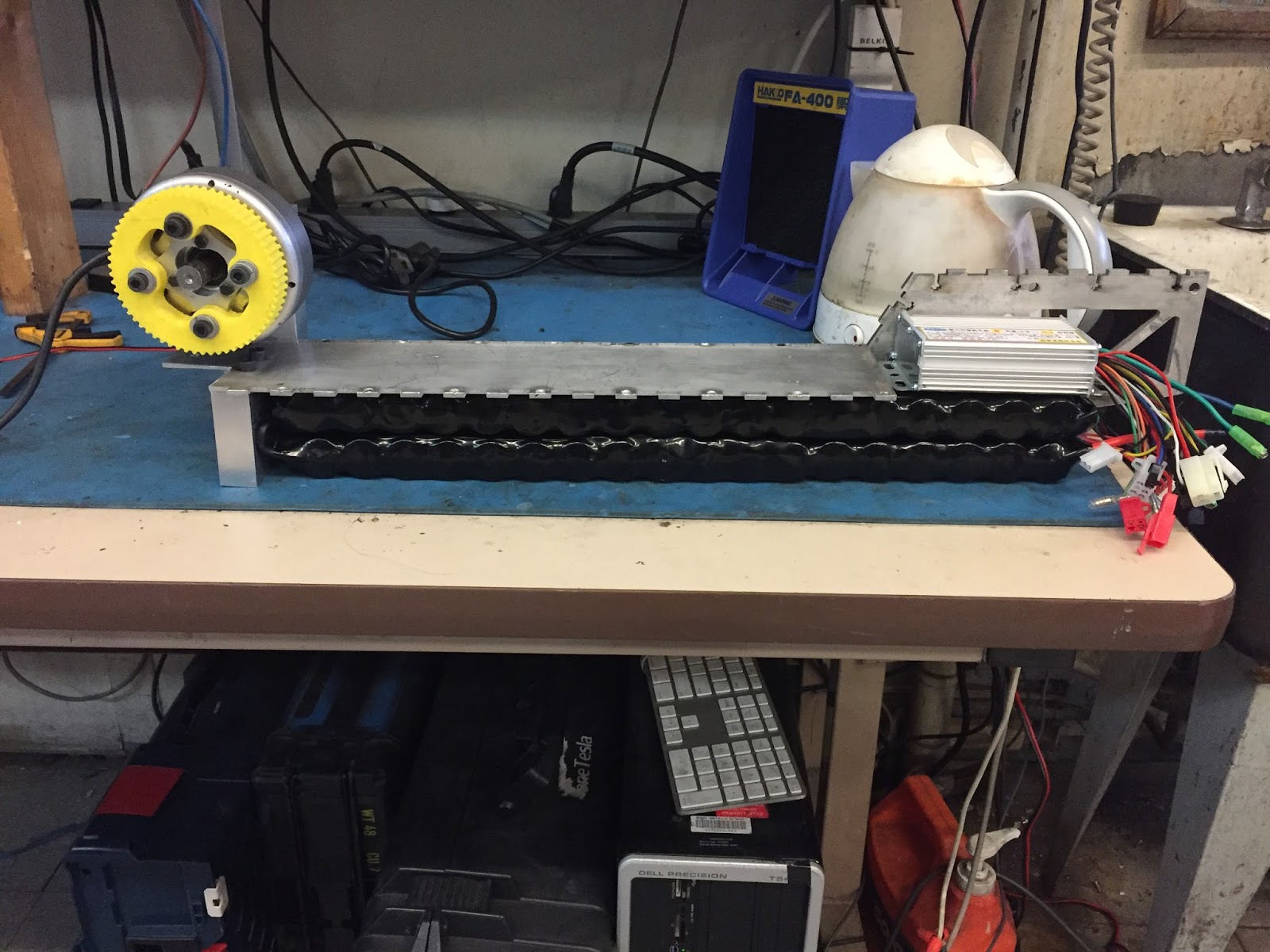
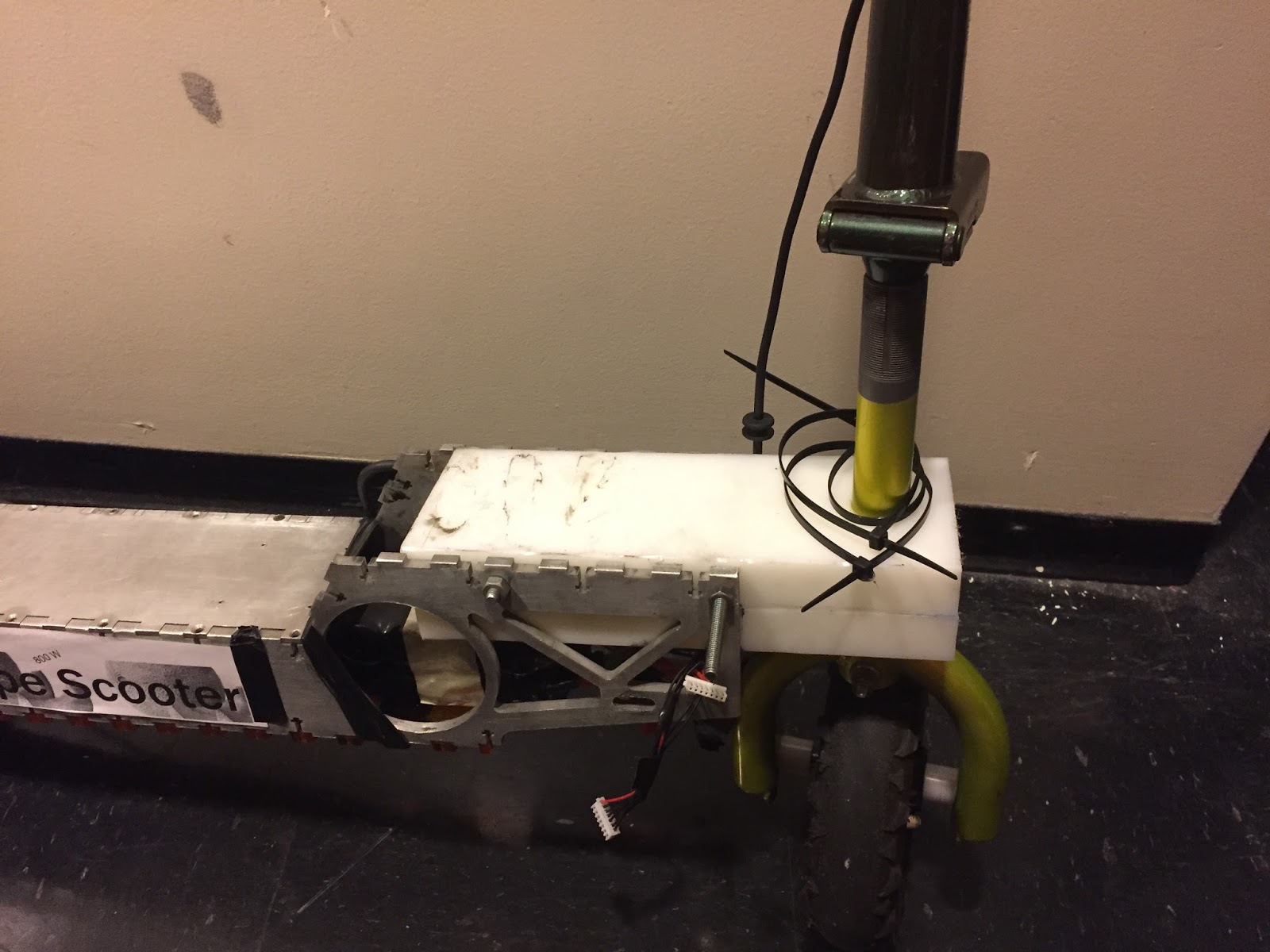
The clamp is used as a battery holder
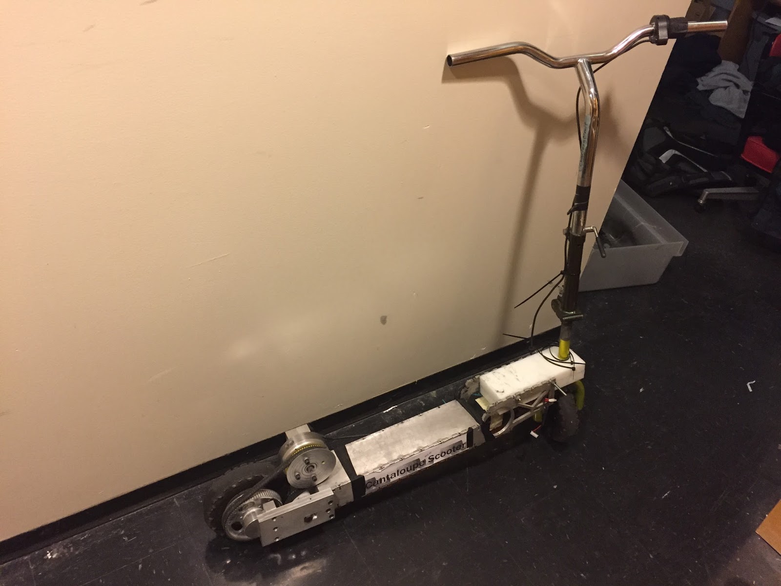
Cantaloupe Scooter is my first attempt to build an electric vehicle at MITERS. The inspiration for the name comes from Charles Guan's Melon-Scooter, which was powered by a "melon" - a "6 kW" brushless outrunner that used to sell on HobbyKing. Cantaloupe Scooter isn't powered by a melon, but does have a cantilevered rear wheel, a cantilevered belt tensioner, and a cantilevered motor and motor shaft.
The main reason I wanted to build an electric vehicle was to have a way to get to and from MITERS quickly. I picked a scooter because it's easy to ride, fairly compact, and can double as a cart to carry heavy items from the loading dock.
Cantaloupe scooter was also built for almost no cost - I only purchased connectors and wire from eBay, which cost around $15. The project was also done without the help of CAD - and as a result has some questionable design. The front part of the scooter was built between the hours of 2 and 5 am, and as a result, isn't quite right. Staying upright at full speed requires a lot of concentration.
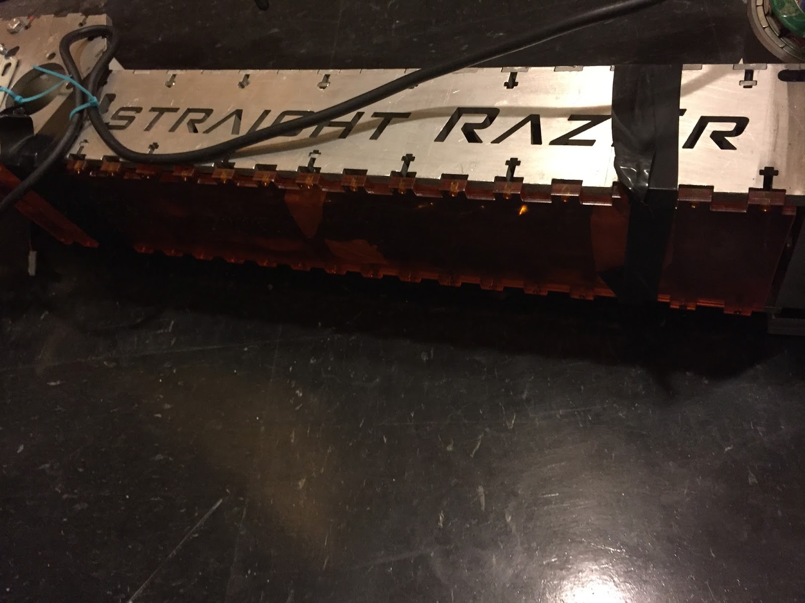
The aluminum used for the sides and top of the frame came from Straight Razer and are almost unmodified. There are a few bonus holes and slots I added to mount the front and rear assemblies.
The acrylic used for the bottom of the scooter is a leftover from some freshman maker class.
I got the HDPE blocks used in the front from the IDC scrap pile. They look like they came from those weird white pedal powered things with a USB logo.
The front fork, handlebars, and wheels came from MITERS.
The belt is a leftover from Frozen Chainsaw Massacre, a powerwheels car that used electric chainsaw motors.
The twist throttle came from a convert-a-bike-to-electric kit found in the loading dock.
The aluminum billets used in the back came out of science equipment found at the loading dock and some plates found in the basement of building 5.
The pulley flange was made out of the lid from some biology equipment.
The bolts, spacers, and nuts came from MITERS.
Half the batteries came from some boxes of "dead" A123's found in the loading dock. Roughly 30 of the 500 batteries were successfully revived.
The other half of the batteries came from a trade - I traded 4 massive 40 Ah 3.3V LiFe batteries for 24 A123's that originally came from reuse.
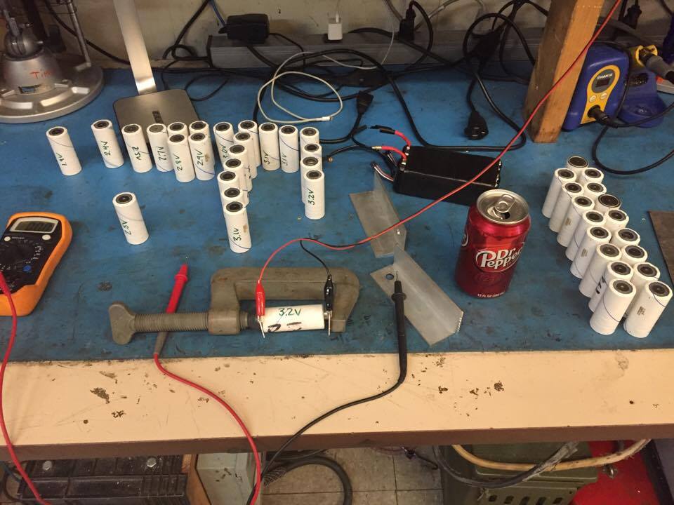
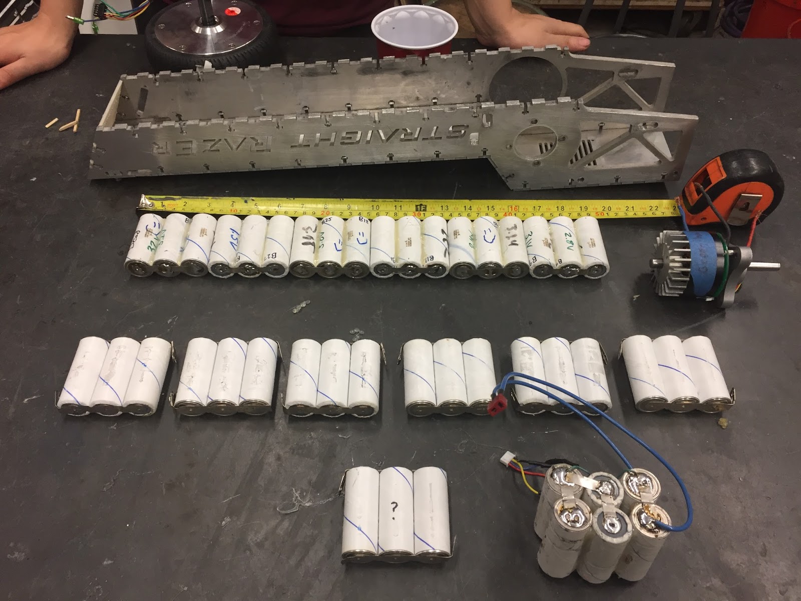
It all started when Alex and I found about 500 A123 batteries at the loading dock. After carting them back to MITERS, we measured the voltage of every cell and ended up with this
The cells to the left all have 1.9V or more, and the ones on the right have between 1.5 and 1.9V. First, the cells were all charged to 3.6V, and were allowed to sit for a week. After, they were discharged on the Dyna-Load at 10 amps.
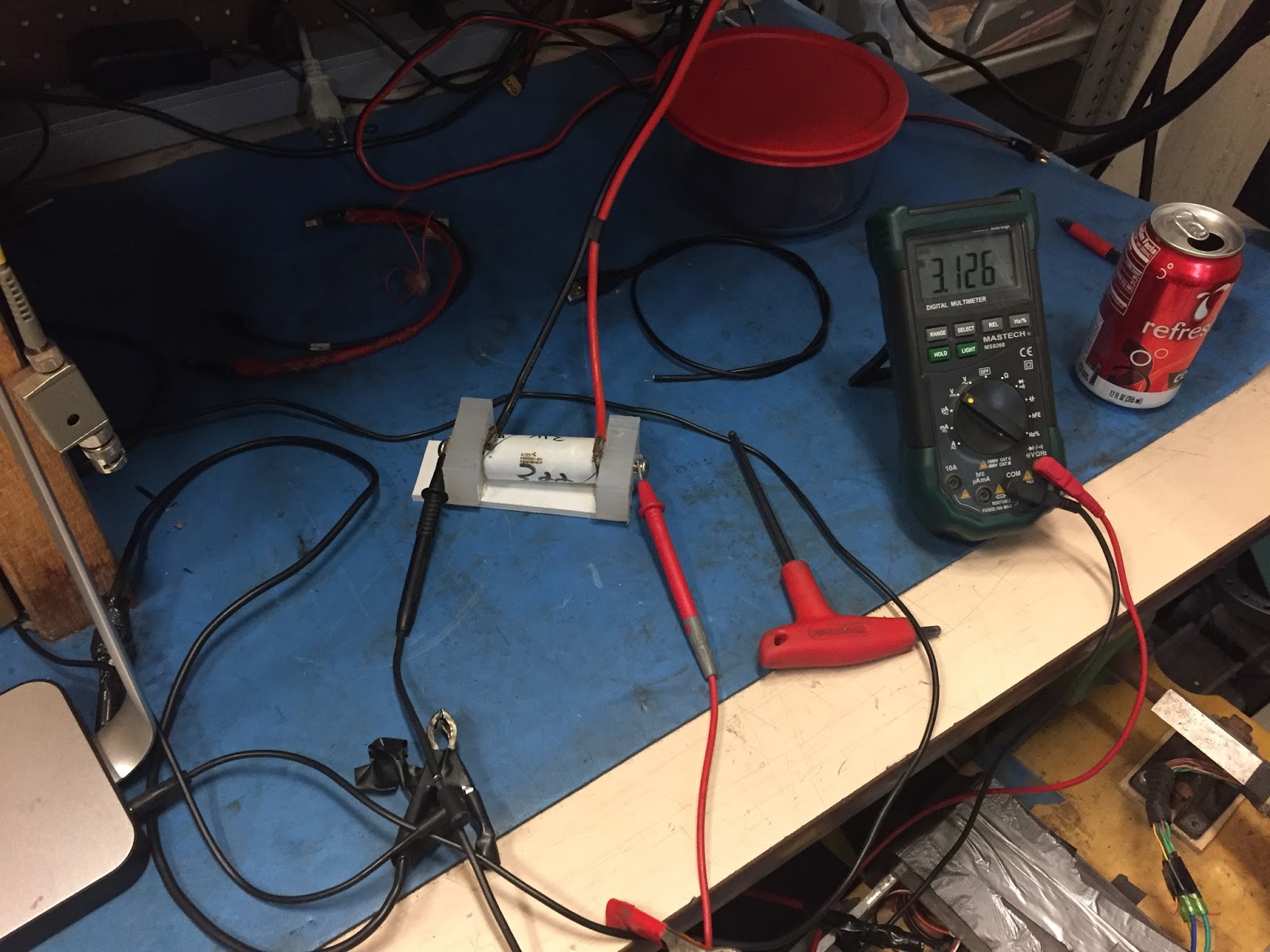
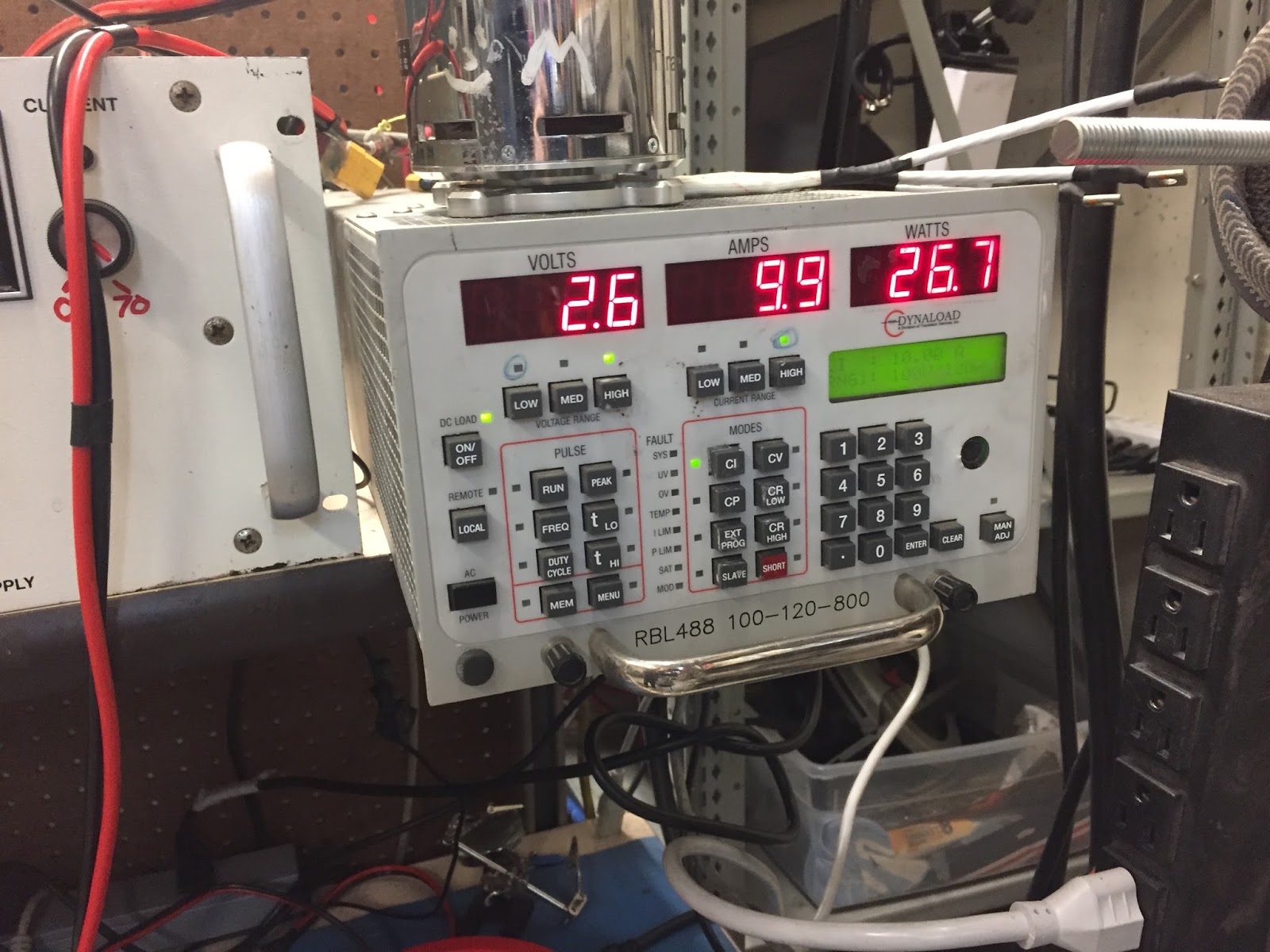
As they were discharging, the cell voltage was monitored by a microcontroller (our favorite stm32f446re), which streamed the voltage over serial at a relaxing 10 Hz to a laptop. The laptop was running plotter, an application I wrote for a motor controller. It plots the cell voltage in real time, and logs it to a CSV file, which can later be opened in MATLAB.
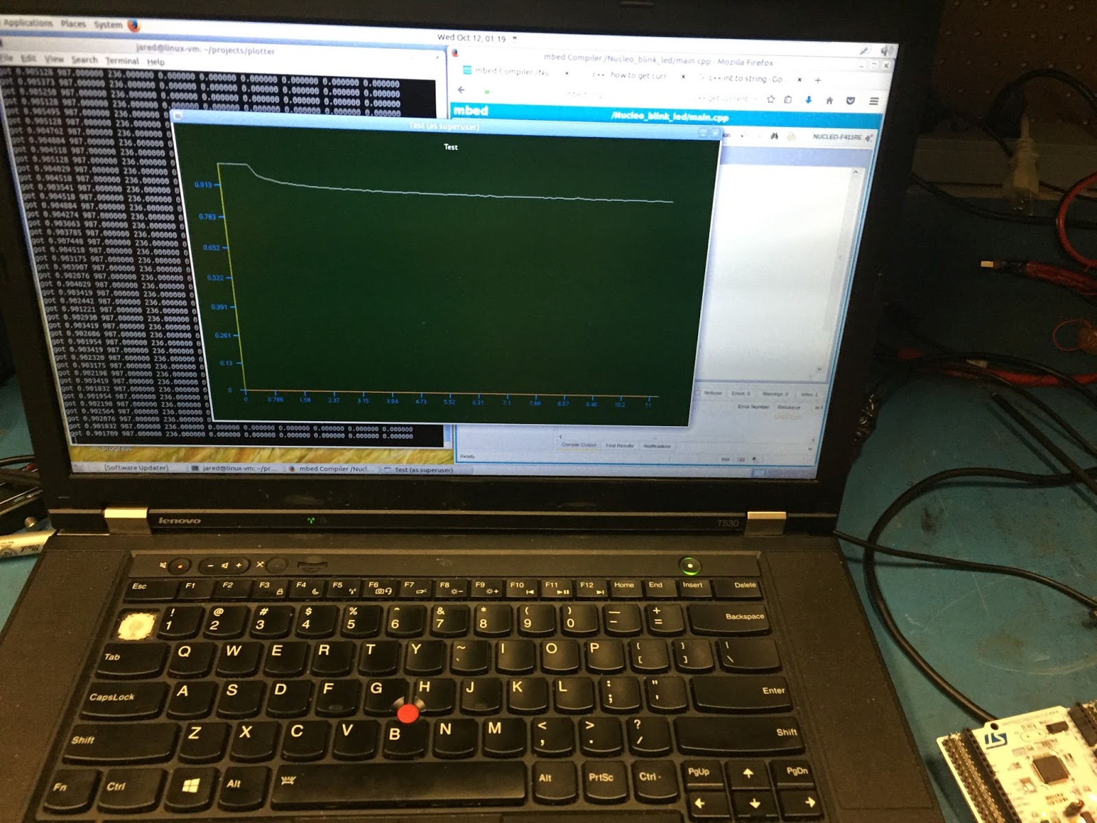
The end result of this charge and discharge test was a big spreadsheet of cell data.
To summarize the results:

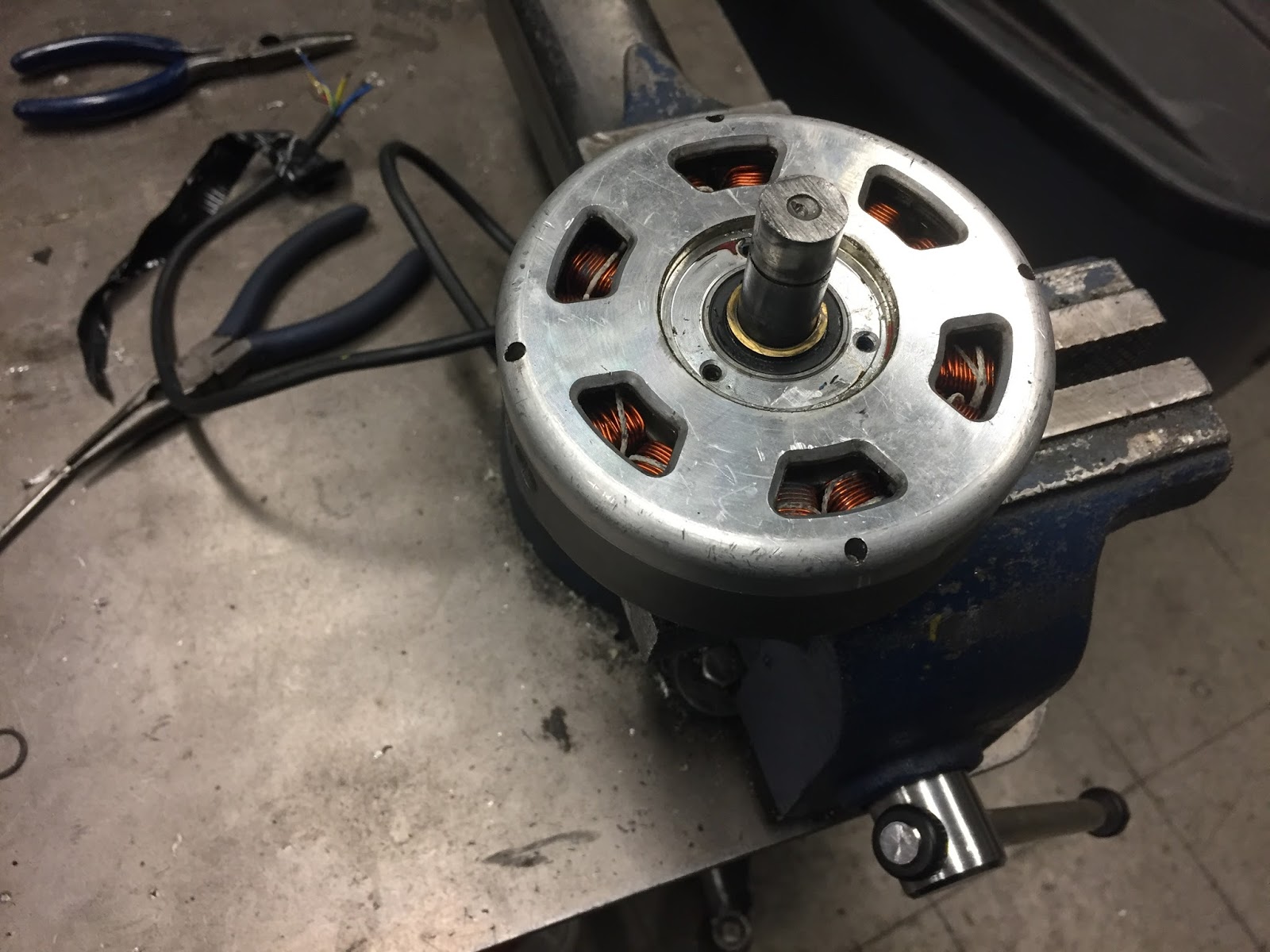
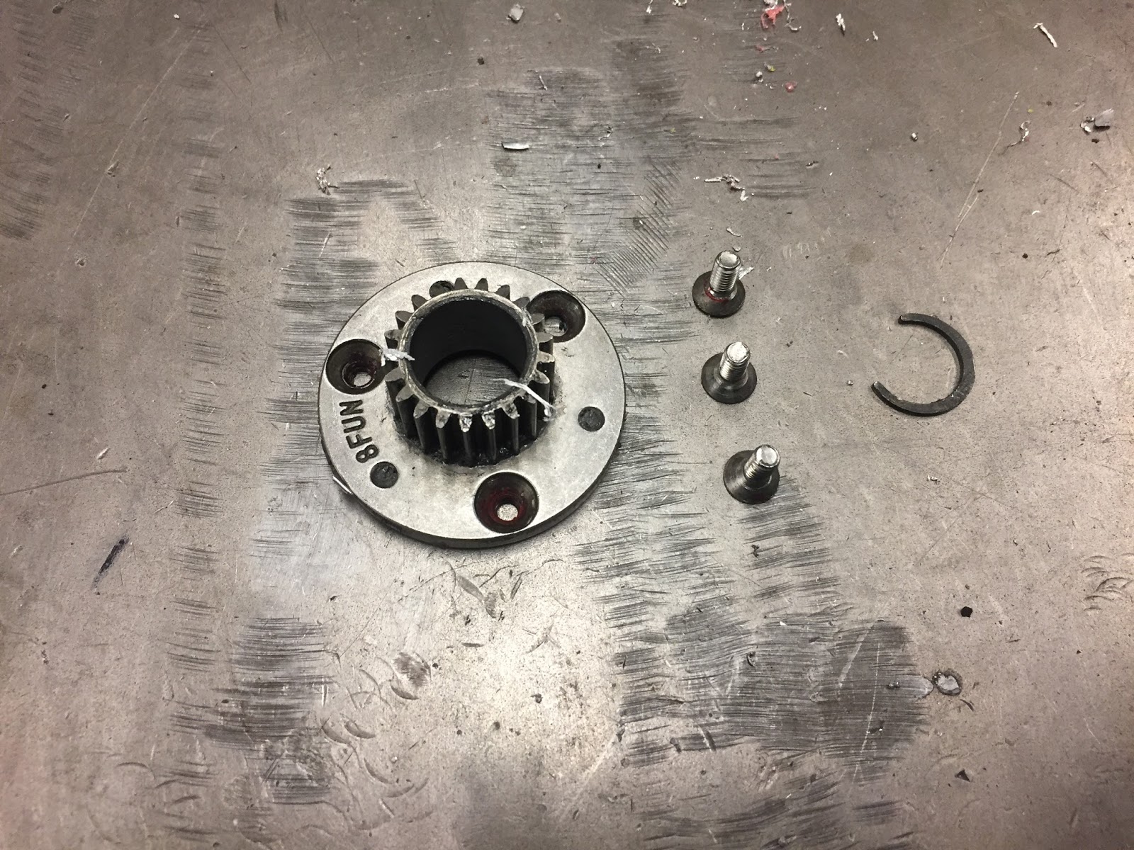
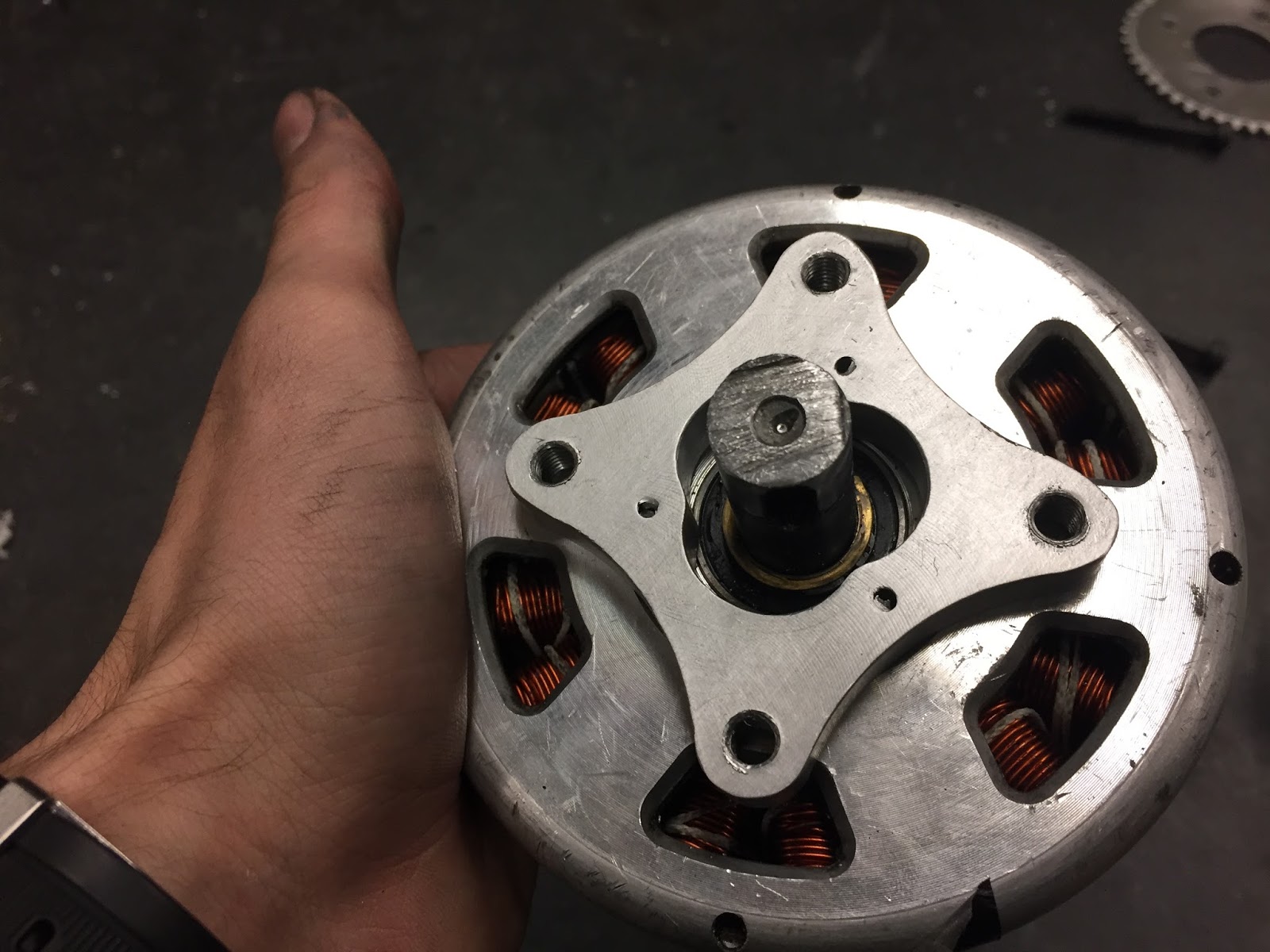
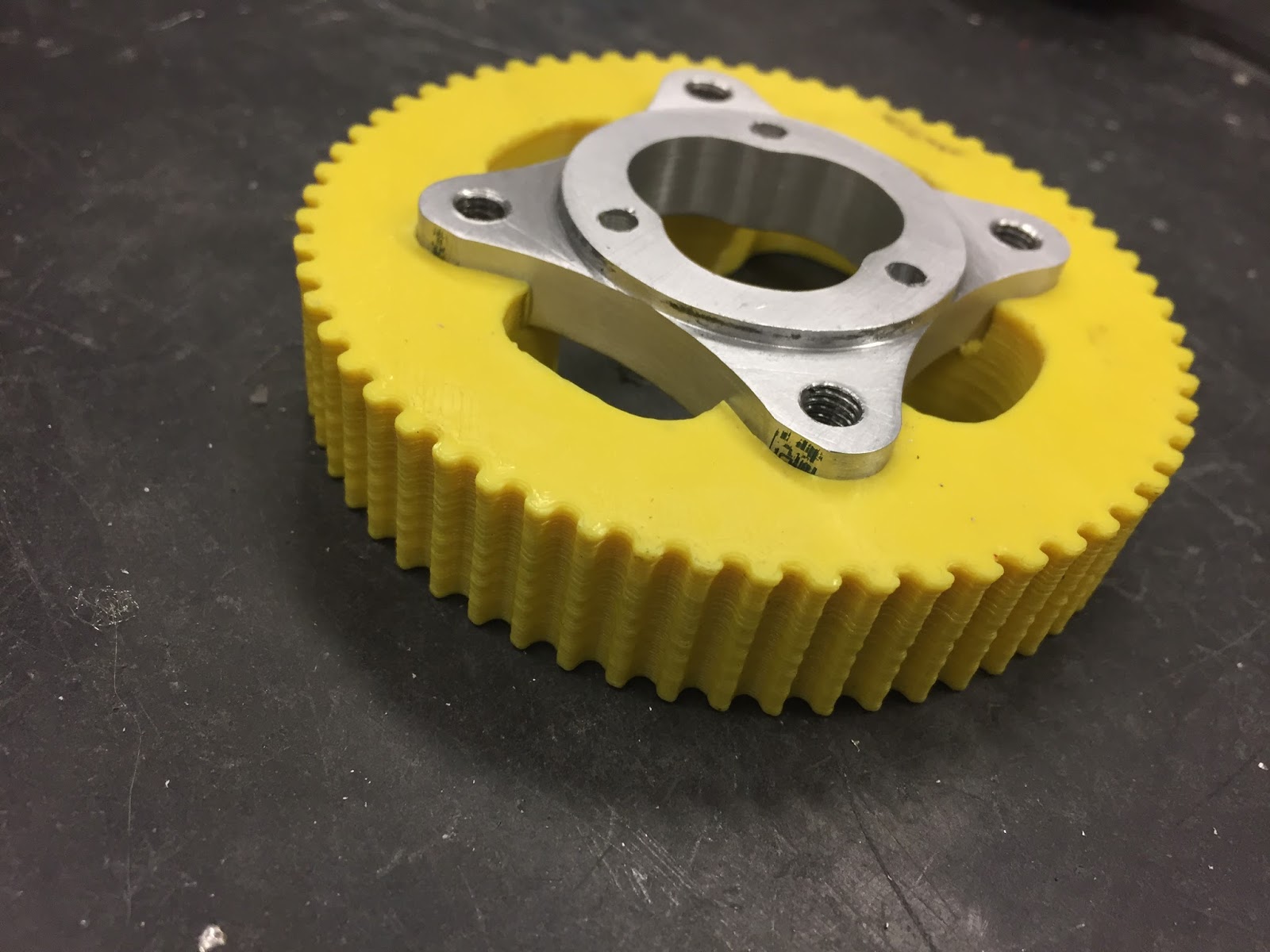
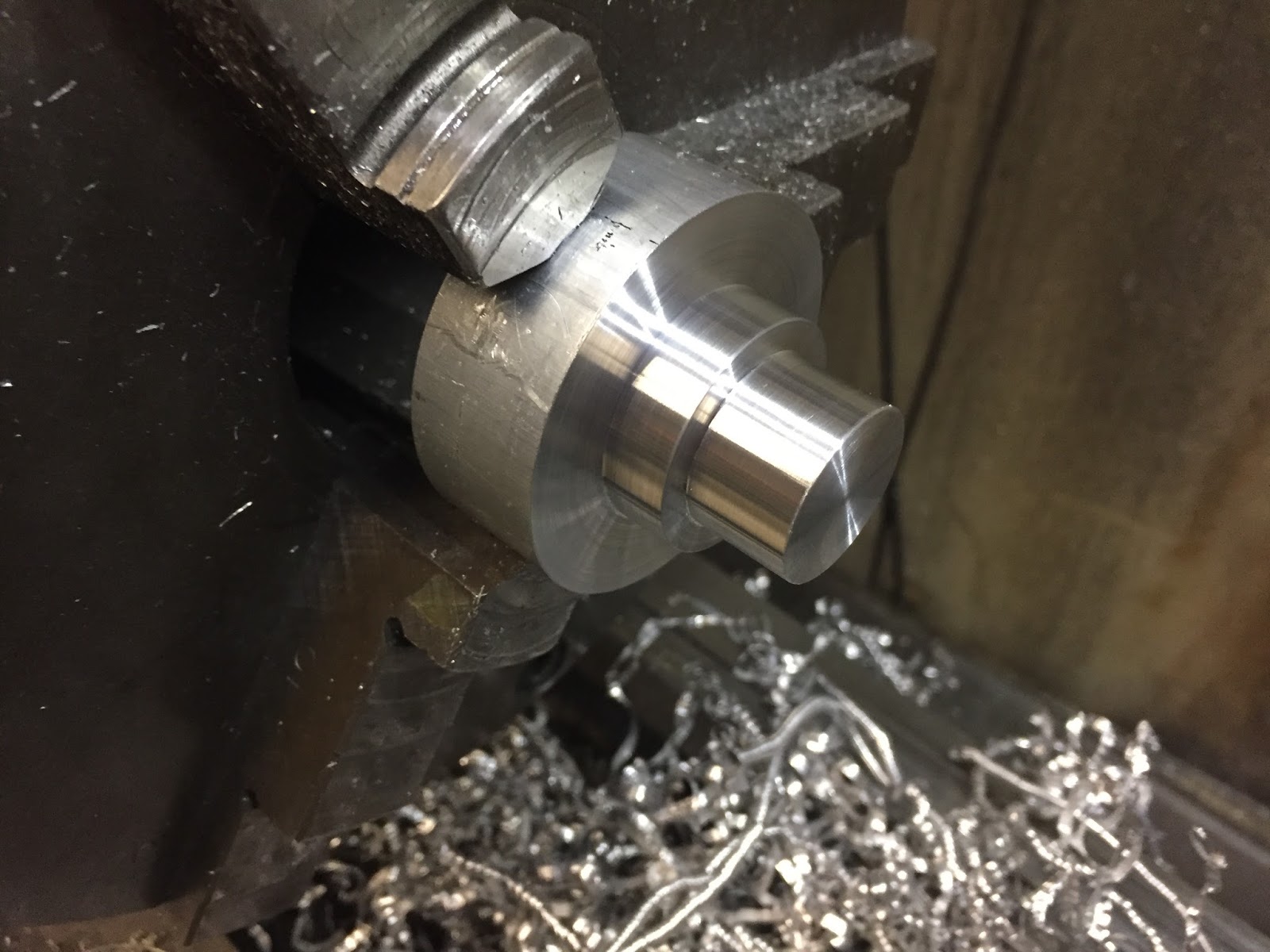
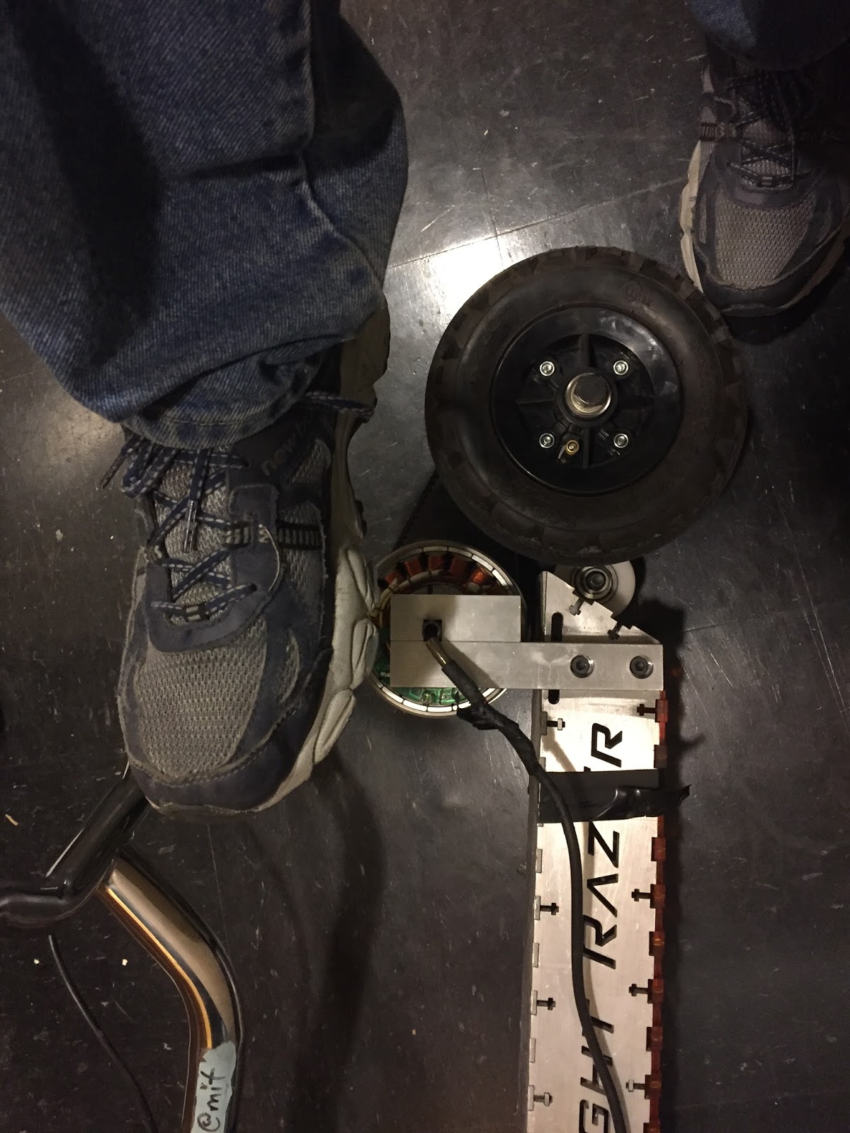
For the drive motor, I used an 8fun brushless outrunner with sheared shaft that came from Dane. This motor is usually used in ebike wheels, and is a great motor for vehicles. Usually, this motor is part of a planetary gearbox, but I removed the gear and CNC'd a new adapter. I was too lazy to CNC a pulley, so I 3D printed one instead. It's a little smushed, but seems to work.
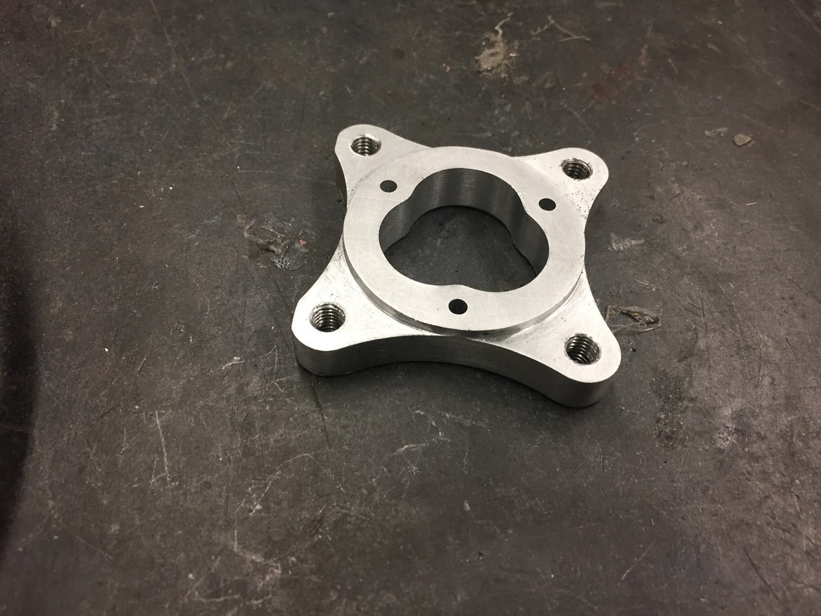
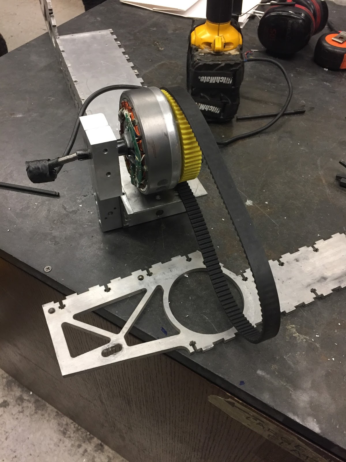
Up next was the mount for the rear wheel. I went with a cantilevered rear wheel because I couldn't find a 10mm bolt that was long enough. The rear wheel mount is shaped like a cake so it can fit into the bore of the wheel.
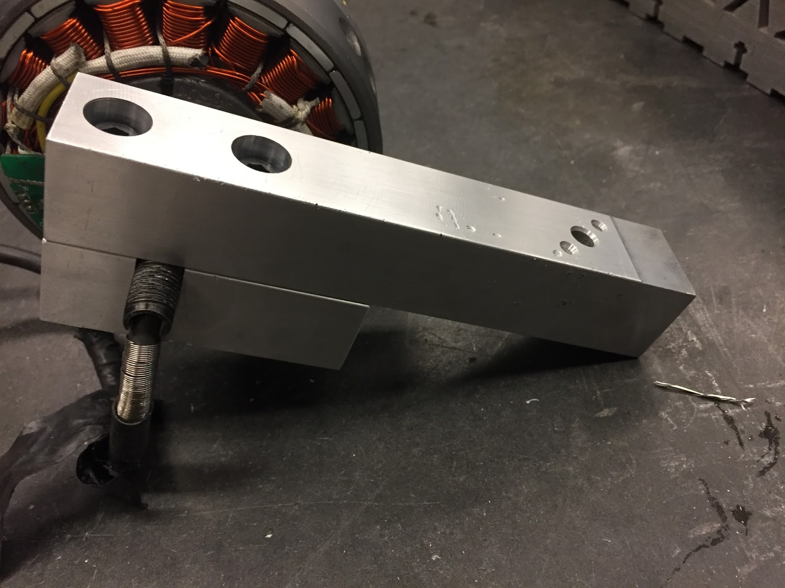
I originally planned to make a cool looking block of aluminum on the CNC that connected the cake to the frame, but this was annoying to design ahead of time. I put the frame of the scooter about 2 inches above the ground, and held everything in place with clamps, and came up with some plans for belt tensionsing and rear wheel mounting.
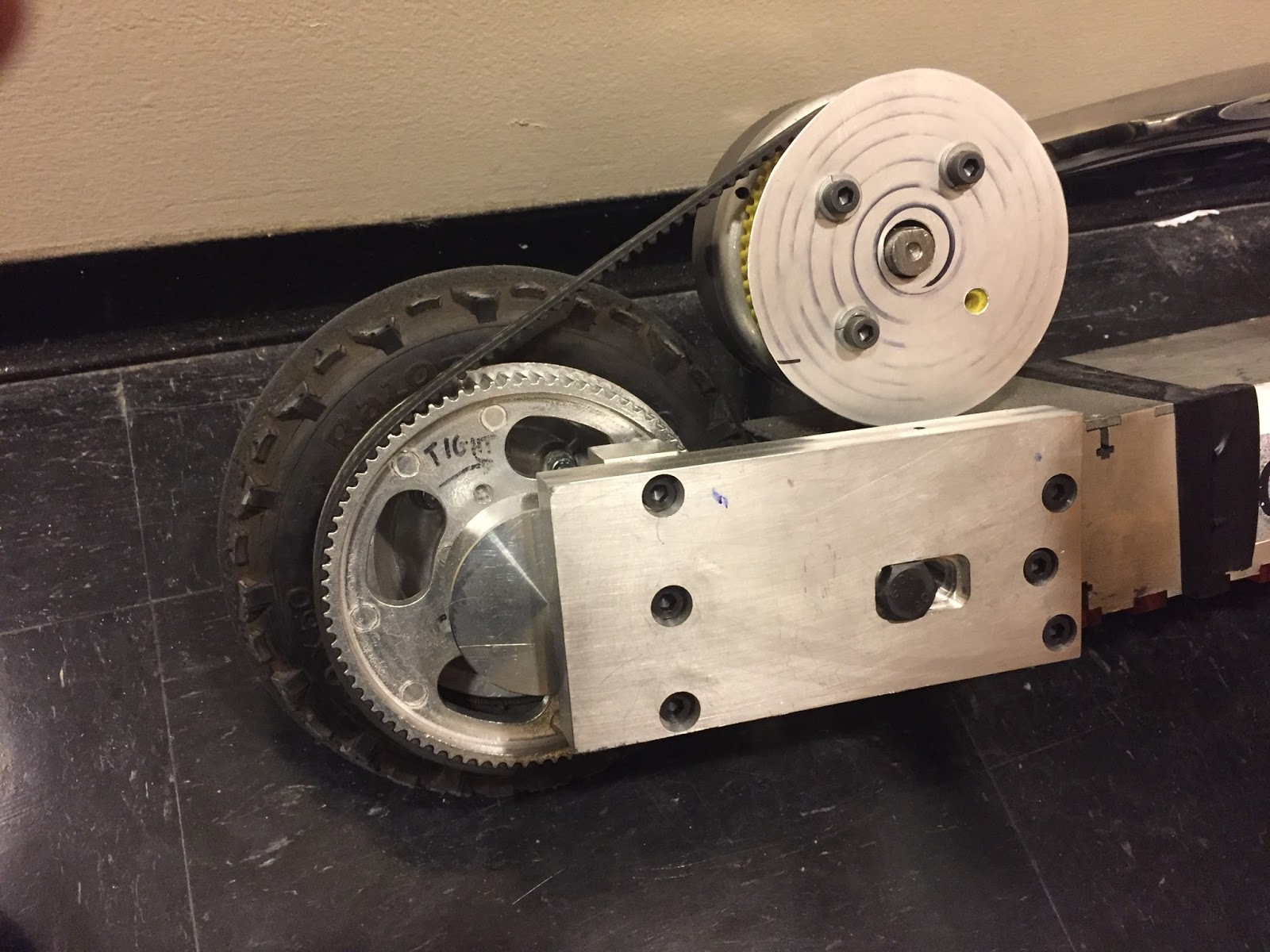
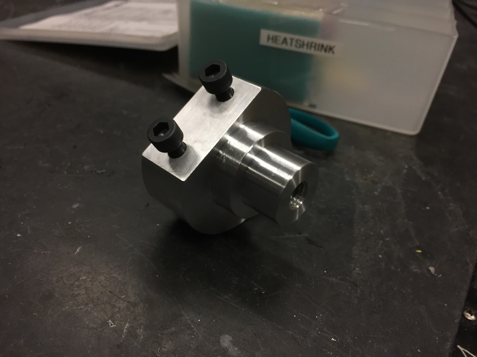
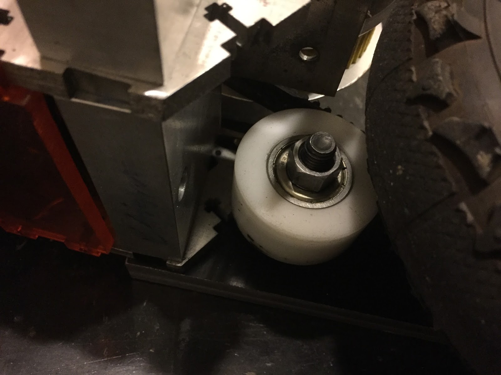
The block connects the frame to the cake, and has a slot for the bolts that serves as the axle for the tensioning pulley. The slightly smushed pulley caused the belt to slip off, so I cut out this roughly circular pulley flange. It turns out MITERS has nothing circular that's 4.5" in diameter to trace a circle with...
The slot for the tensioner is designed so the head of the bolt won't spin.
The front of the scooter is a total disaster. I took some huge chunks of HDPE, made them roughly the same size, then drilled a 1" hole at a roughly 5 degree angle.
The completed scooter has a a current top speed of around 18 mph, and a range of around 5 miles. At high speeds, it's a challenge to keep everything stable due to the excessive steering friction. I'm hoping the HDPE wears out over time.